Music industry’s 1990s hard drives, like all HDDs, are dying
Music industry’s 1990s hard drives, like all HDDs, are dying
Open link in next tab
Music industry’s 1990s hard drives, like all HDDs, are dying
https://arstechnica.com/gadgets/2024/09/music-industrys-1990s-hard-drives-like-all-hdds-are-dying/
The music industry traded tape for hard drives and got a hard-earned lesson.
Excellent Mastodon post: why does heating an XBox controller fix it? MLCC Capacitor chemistry, physics, heat infodump.
Excellent Mastodon post: why does heating an XBox controller fix it? MLCC Capacitor chemistry, physics, heat infodump.
Open link in next tab
Graham Sutherland / Polynomial (@gsuberland@chaos.social)
https://chaos.social/@gsuberland/113084315488845513
@greg@icosahedron.website oh oh oh I get to infodump about my favourite thing! it's nothing to do with solder. it's capacitors!
Firmware extraction from PIC16F using MPLAB X and Pickit3; BIN is all zeros
Firmware extraction from PIC16F using MPLAB X and Pickit3; BIN is all zeros
I have been attempting to extract the firmware from an HVAC controller board using my Pickit3 and MPLAB X.
It seems that many HVAC controllers are PIC based and most are kind enough to include debug/flash pins. Grabbing the firmware images should be trivial once the correct pins are traced out. MPLAB X will see my Pickit3 and the target MCU, but it fails to pull an image that isn't all zeros. (The "bin" file is a text file with each line noting the start address, followed by 16 byte values.)
I do get an occasional "Target device ID invalid message" but that is usually due to my janky wiring to the board. Once I get that issue cleared, MPLAB will always warn that the debug bit (byte?) is set on the MCU. (That doesn't make sense as the MCU should be running standalone on the board during normal operation.)
Is there some kind of read protection that may be enabled on the PIC? Do I just need to unsolder the PIC and put it in its own dedicated circuit for pulling the firmware?
Quick notes on Microchip's MCP9700 / MCP9701 Temperature Sensor
Quick notes on Microchip's MCP9700 / MCP9701 Temperature Sensor
Just working on my recent electronics project and I needed two temperature sensors for it. This time around I didn't feel like making a full PCB from KiCAD and wanted to keep things simple with a 1/2 size solderable breadboard.
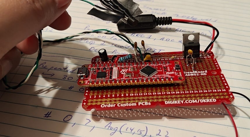
As usual, I'm using an AVR DD (this time: a curiosity nano devboard) for simplicity. (I expect to need the 32768 Hz clock crystal, so a PCB with said clock would be nice. Otherwise, the DIP package is available). The overall circuit is pretty simple, but the topic of discussion today is the MCP970X series temperature sensor.
https://www.microchip.com/en-us/product/mcp9701a
At this point I do recommend people to read the documentation.
The gist is that you simply apply 3.1V to 5.5V between Vdd and Gnd. Vout will have some amount of startup time, and eventually output 400mV + (Temperature-in-C * 19.5mV). For example, my room temperature is ~24C right now and the voltage output is ~920mV.
(There's clearly errors in my ADC but I'm saving that for later... this device is supposed to be outputting 876mV given the room's temperature)
With a ~6uA expected current, this device is power-efficient enough to run from most MCU pins. AVR DD's 50mA-per-pin is overkill, but more importantly, a through-hole design like mine seemingly has substantial inductance on all wires.
The datasheets claim a startup time of 0.8ms. Alas, when I soldered on the MCP9701 and turned on the GPIO-pin, it took over 20ms (!!!) before the oscillating signal finally calmed down and settled upon the room temperature reading.
To counteract this parasitic inductance, I've added a 10kOhm resistor and a 10nF capacitor out of my through-hole kit. (E12 resistor kit and E6 capacitor kit). With 220us of startup time now on the GPIO pin and with only 500uA max current going to Vdd... there is no more "ringing" anymore and life is good!
EDIT: I should probably note that my goal was to return to 0.8ms startup time, like the documents suggest. 10kOhm was chosen as 500uA (5V) to 250uA (after charging to 2.5V) is a magnitude more current than I need and is a decent starting point. 10nF was chosen to pair-up with this to give me startup time in the 100us range but not over 800us (I don't want to be "slowed down" by the charging capacitor, so I want the Vdd charge to be faster than 800us claimed startup time). It should be noted that a 5V over 1000us curve was claimed as a 800us startup in the MCP970x documents if you read all the graphs.
Moving forward, my last task is that of calibration. The on-board ADC of the AVR DD is apparently quite accurate, but the Vref of the microcontroller is +/-4% (!!). With a +/- 2% accuracy of the temperature sensor, there is some calibration I should do.
The ADC errors + Vref errors are expected to just be linear. The temperature-sensor's error is quadratic however. In both cases, I don't want to overcomplicate things, so I'm planning on just adding a constant-offset to the mV reading to shift it to the correct spot.
All in all: pretty standard Analog-to-digital conversion issues here. But I figured it'd be a good discussion topic for beginners.
How to Select a Timer on AVR MCUs
How to Select a Timer on AVR MCUs
Open link in next tab
https://www.microchip.com/en-us/about/media-center/blog/2024/how-to-select-a-timer-on-avr-mcus
Nyquest NY8A051H - 1.5 cent microcontroller : weekend die-shot : ZeptoBars
Nyquest NY8A051H - 1.5 cent microcontroller : weekend die-shot : ZeptoBars
Open link in next tab
Nyquest NY8A051H - 1.5 cent microcontroller : weekend die-shot : ZeptoBars
https://zeptobars.com/en/read/Nyquest-Technology-NY8A051H-8051-smallest-microcontroller
[popovicu] Making my first embedded Linux system
[popovicu] Making my first embedded Linux system
Open link in next tab
Making my first embedded Linux system
https://popovicu.com/posts/making-my-first-embedded-linux-system/
End-to-end documentation of a journey from no PCB experience to fabricating my own Linux-ready system that can boot the latest mainline kernel. This article is the recommended reading for someone building their first embedded Linux board. F1C100s SoC is used for this sample board.
Batteryless UV Index (UVI) and Heat Index Monitor with AVR32DB32
Batteryless UV Index (UVI) and Heat Index Monitor with AVR32DB32
Open link in next tab
GitHub - microchip-pic-avr-examples/avr32db32-uv-monitor-mplab: Create a portable, solar-powered UV monitor with AVR DB.
https://github.com/microchip-pic-avr-examples/avr32db32-uv-monitor-mplab
Create a portable, solar-powered UV monitor with AVR DB. - microchip-pic-avr-examples/avr32db32-uv-monitor-mplab
Making USB devices - end to end guide to your first gadget
Making USB devices - end to end guide to your first gadget
Open link in next tab
Making USB devices - end to end guide to your first gadget
https://popovicu.com/posts/making-usb-devices/
Introduction to implementing USB devices. Minimal overview of hardware and software with an example with STM32 microcontroller. Also contains an index to very detailed guides for more information.
Building And Testing A 1912-style Radio - Hackaday
Building And Testing A 1912-style Radio - Hackaday
Open link in next tab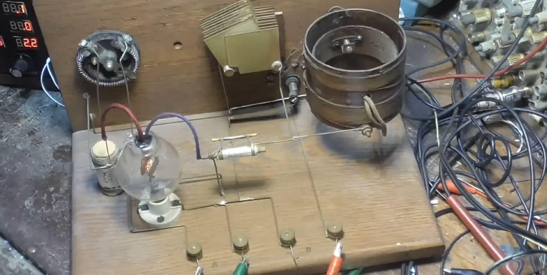
Building And Testing A 1912-style Radio
https://hackaday.com/2024/06/02/building-and-testing-a-1912-style-radio/
Doing electronics in the 1910s was rather rough, with the radio probably the pinnacle of hi-tech. Despite this, with some know-how and basic wood- and metal-working skills you could get pretty far …