What's the best way to add a battery like device to a dynamo light
Hello everyone, I bought a bottle dynamo for my bicycle with a rear and front light. Though I have one little tweak that I would like to add and that's a way to keep it light up for about 1 minute (at least 30 sec) without pedaling. I thought of putting a capacitor in the circuit to store some energy but I would like what do you all think of it ?
Thank you for your time and have a nice day you all !
Can I charge a 19V laptop from multiple USB ports?
Can I charge a 19V laptop from multiple USB ports?
My laptop's charger is rated at 19V 2.1A. I was wondering if it would be possible to build an adapter which would allow me to charge it from a power bank, even if just slowly or via multiple USB ports.
I know you can buy adapters which utilise USB power delivery, but most outlets and powerbanks don't have PD yet.
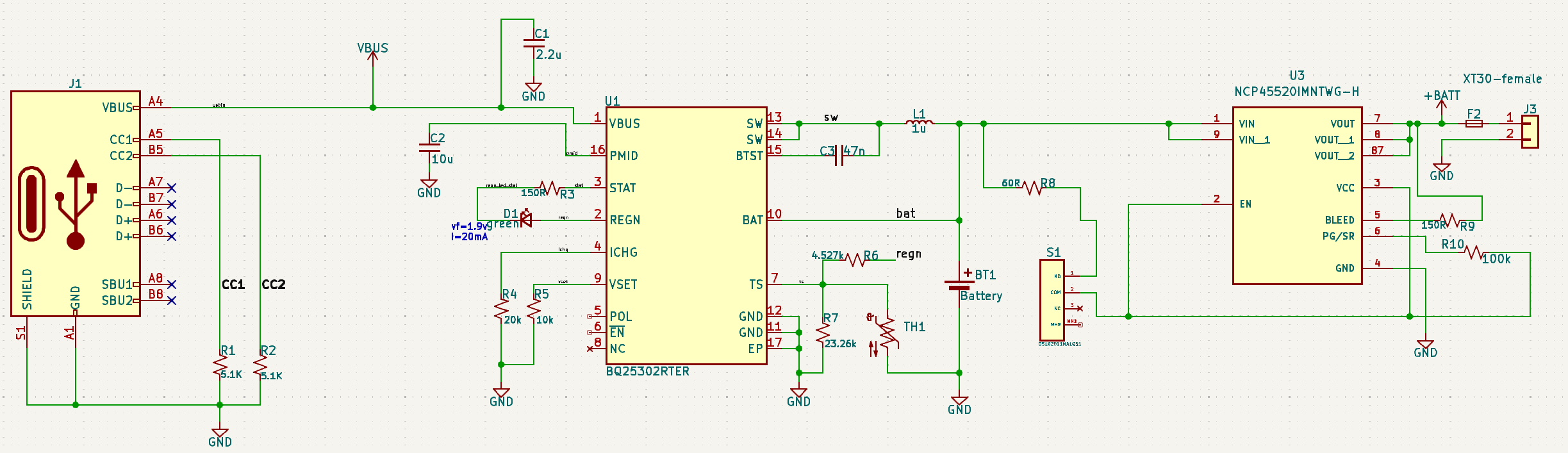
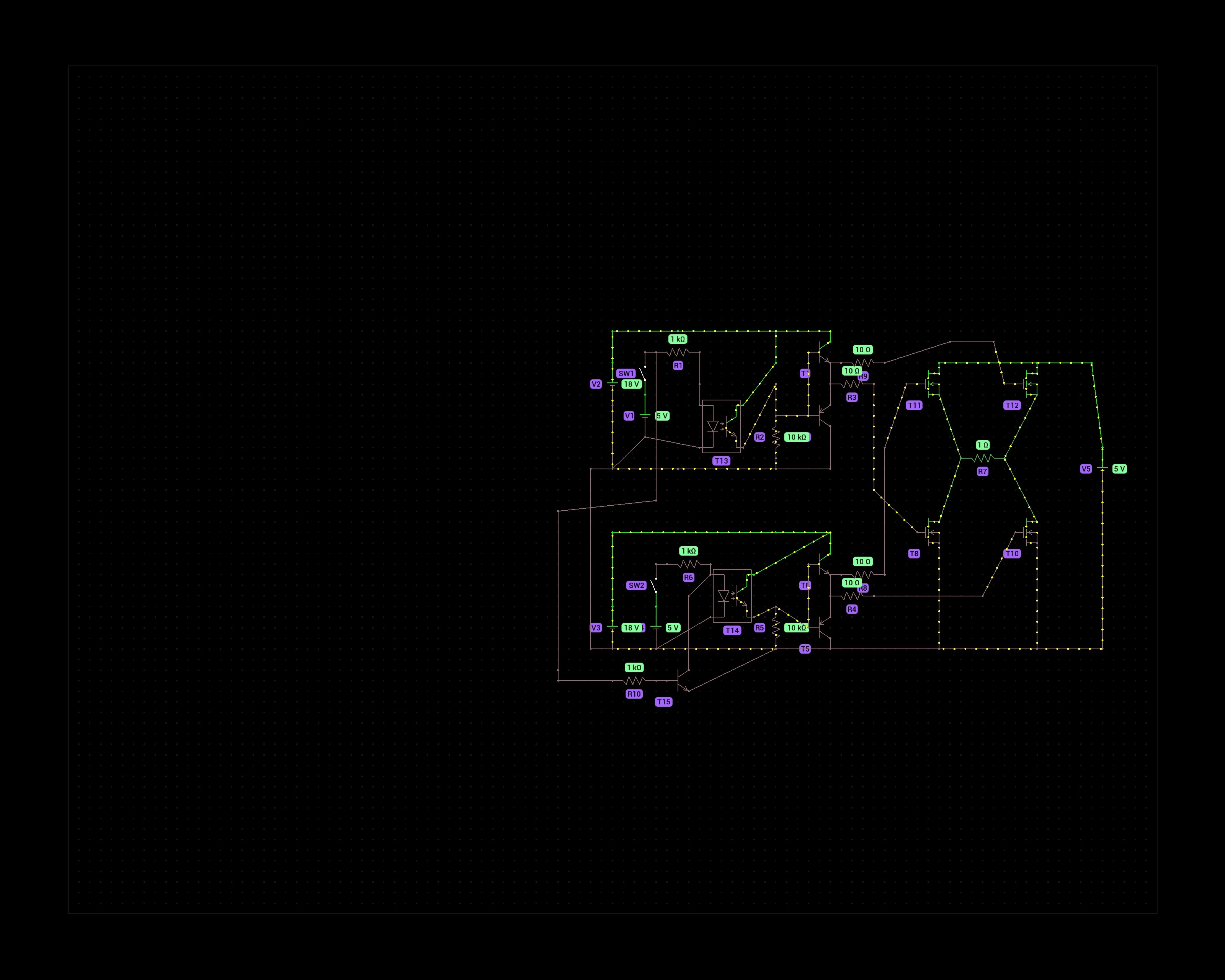
Schematic problem - It gets hot and smells like burning
I've been messing around with circuits my entire life but this design was time sensitive and I've never done my own PCB designs before, so I hired someone to put this together. After getting some test boards, when I plug them in the charger chip gets very hot and smells like burning....
Circuit is just a simple li-ion usb charger and a switch. I've gone through the datasheet for the bq25302 more times than I can count and I'm missing something obvious here. Using it just for delivering power seems to work fine, the problem is only when charging.
I do see R6 + R7 off TS don't have the recommended 10k values, but I don't feel like that would cause what I'm seeing. This is being connected to a 21700 lipo.
Someone mind lending me their eyes please?
bq25302 datasheet - https://www.ti.com/lit/ds/symlink/bq25302.pdf
Does anyone know if there's an IR/RF dimmer available in any of the Chinese online stores (AliExpress and the likes)?
A simple thing like this, but premanufactured. I scoured the internet trying to find one (at a reasonable price) and there is nothing. I would make one myself, but I just don't have the time currently to do that.
I need it for a mains fan control. Doesn't have to be fancy (all of the ones I encoutered were very fancy, with touch sliders and whatnot), 5 steps is enough, on/off control as well as speed control through the remote. Nothing fancy, as I said, 5 steps is more than enough. So, basically, just 3 buttons on the remote: on/off, + and - is all I need.
Also, I don't need smart/phone/app solutions, I would like it to just have a remote, that's it.
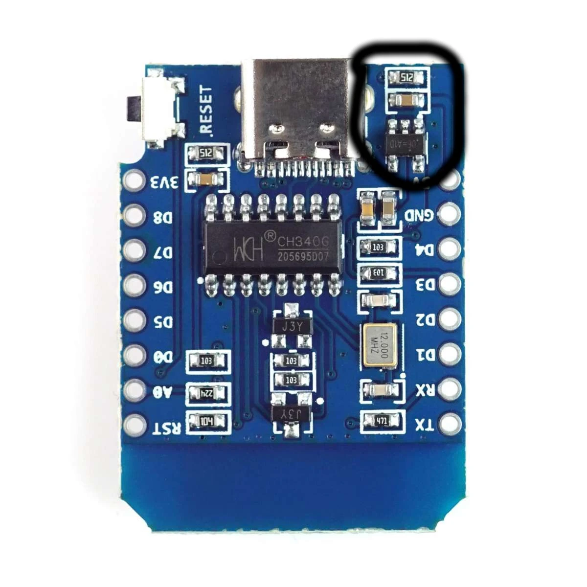
How much current can I safely pull from an ESP8266?
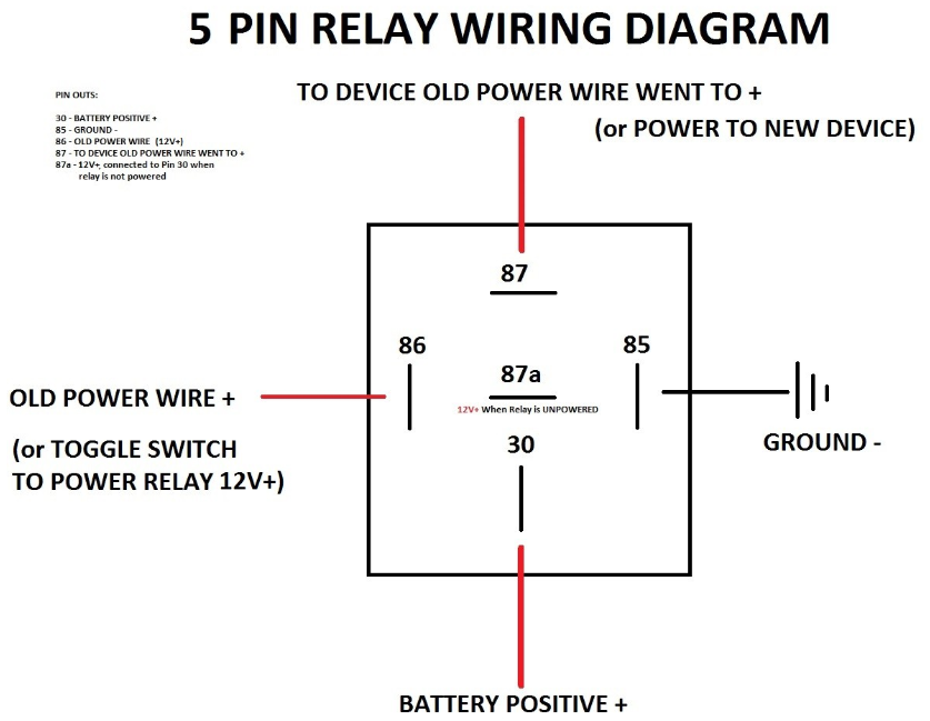
Is there such a thing as an automotive relay with no resistor?
I've been trying to solve an automotive electronics problem for several weeks now, but everyone I've spoke to can't seem to come up with a solution.
In brief, I'm trying to add a relay in-line with the horn switch in my car, such that I can close my own circuit when the horn is pressed, without affecting the existing horn circuit in the car.
I had some JD1912 12V relays left over from a previous install, so I tried to use those. (Relevant image: Diagram)
First, I placed connected the trigger wire (pin 86) to the the wire coming into the horn switch, and the ground (pin 85). The relay triggered when the horn button was pressed as expected, but this also caused the actual car horn to sound continuously. Presumably doing this was enough to give the factory horn relay enough current to close.
Next, I tried placing the relay in series with the horn switch by splicing the wiring heading into the horn switch, and connecting the relay (pin 86 and 85) in line. Once again, the relay triggered with the horn switch as expected. However, this time, the actual car horn didn't sound at all.
The best I can work out is that there's a resistor in-line with the relay trigger (otherwise connecting it straight to ground would cause a short, right?) However, that resistor is just enough to allow the factory horn relay to trigger when connected to ground.
The way the car is designed, I can't splice into the wire coming out of the switch to detect when the horn is pressed, since it's a shared ground with other components.
My question is, is there such a thing as a relay with no resistor? Essentially all I'm looking for is a component that will "detect" current on the horn switch wire, and close a separate circuit. I'm not sure if a relay is even the correct way to go about this. Hopefully you guys can point me in the right direction.
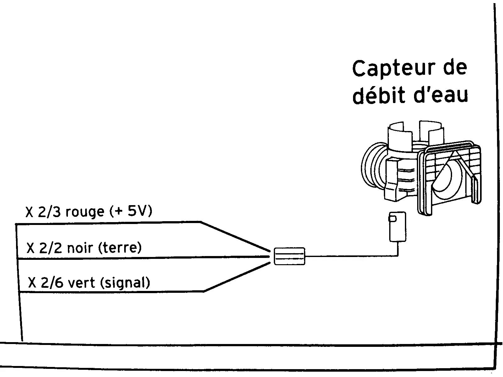
[solved] help needed to understand this diagram of a water flow sensor (from a boiler)
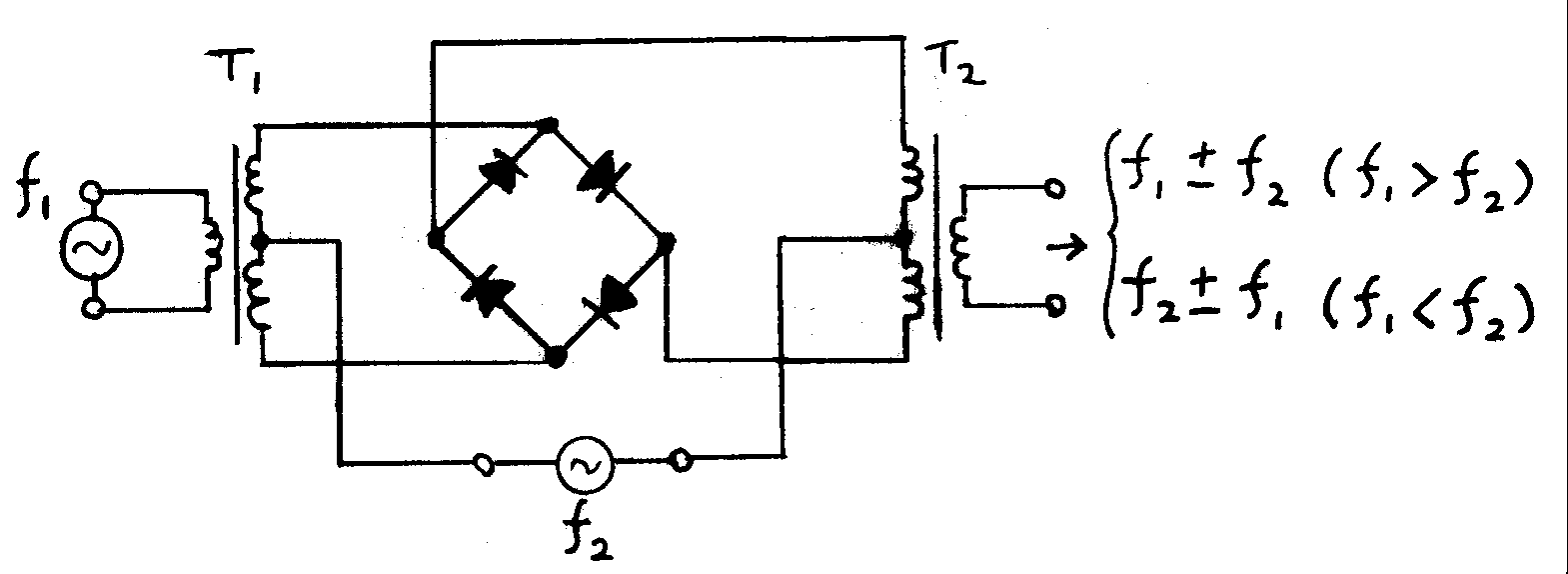
How do I select a transformer for superhet?
I've recently been learning about superhet and frequency mixing and wanted to start tinkering. Specifically I'd like to try using two heterodynes in series to first frequency shift then uninvert the original audio, sort of like an analog frequency shifter.
To do this, I'd need a frequency mixer. I've been looking at a ring modulator (like https://upload.wikimedia.org/wikipedia/commons/1/1b/Diode_DBM.png) which should require 4 shottky diodes and 2 center-tapped transformers. I've had difficulty locating an affordable transformer, with good enough fidelity for audio, that also includes a center tap.
I have a few questions:
- Where can I locate affordable, good-enough-for-audio transformers?
- Is the ring mod approach good enough? I see there's also a gilbert cell.
- Any general advice for someone just starting a project like this?
Thanks!
DC motor speed control
I'm trying to achieve variable speed control on two brushed DC motors powered by a 3s or 4s LiPo battery (~12V or 15V). This is for a nerf blaster I'm modifying, which is why I'm not using a pre-made speed control ie I want control over the shape/layout. I'd like to vary projectile speed with a thumb knob.
I just finished watching ElectricMonkeyBrain's YouTube video on the TL494 PWM chip.
I was initially planning to vary the duty cycle with a potentiometer on the chip's control pin, to get a PWM signal and feed that into a MOSFET. But in the video he mentions that the chip has an integrated over current protection function. Ie the chip will
monitor the voltage across a sense resistor in series with the load
and will
kill the output if the sensed voltage/current goes above a reference voltage
It occured to me that I could actually adjust the reference voltage as a way to control the motor speed.
Would this be a better way to achieve speed control and protect my motors/battery? Or is it a terrible idea altogether.